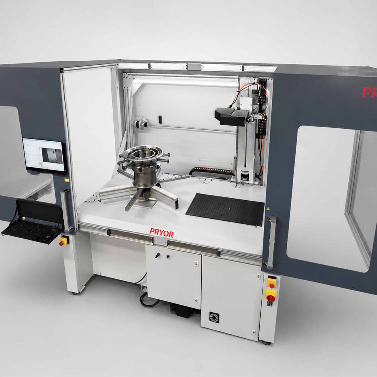
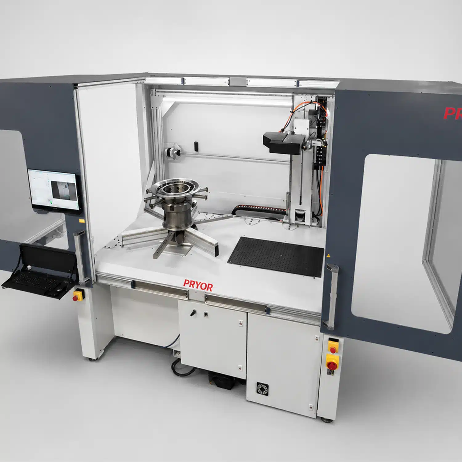
An aero engine disc rarely gives you a flat face to work with. Casings, blisks and turbine rings come with curves, bores, internal diameters and angled faces that a fixed marking head simply cannot reach. On a component where a misplaced or unverified mark can mean rework, concession or scrap, that’s not a detail. It’s a major problem that our Multi Axis Aerospace Workstation was designed and built to solve.
This article looks at why complex aerospace geometry demands a different approach to marking, how vision-guided alignment and integrated verification work together to protect mark quality, and where this kind of system earns its place on an aerospace production line.
Why Aerospace Marking Carries More Risk Than Most
Engine components are marked because they have to be traceable for life. The mark has to sit in the right position, meet the right quality standard and match the right production data, every time. Get it wrong on a high-value casing or disc and you’re not looking at a quick fix. You’re looking at rework, a concession process, or in the worst case, scrapping a component that may have cost tens of thousands of pounds to machine.
That’s the standard our engineers design against. Not “mark it well most of the time,” but mark it right, in the right place, and prove it.
Designed for Complex Aerospace Components
The workstation is built for the part families that cause the most trouble on conventional bench-mounted or fixed marking systems:
Engine casings
Engine discs
Blisks
Turbine rings
Structural rings
These are components that are high value, awkward to handle, irregular in shape, or governed by aerospace direct part marking requirements. A fixed-head machine asks the operator to bring the part to the mark. Our workstation does the opposite. It controls up to eight servo-driven axes, including horizontal, vertical and rotary movement, working alongside an adjustable turntable, so the marking head and the component can be positioned together for the access angle the job actually needs.
In practice that means external faces, internal faces, angled faces, recessed surfaces and multiple faces on the same part, all from one machine, without re-fixturing between operations. Most multi-axis marking systems in this space top out at six axes. Controlling up to eight gives our engineers more freedom to set the marking head and the component to exactly the angle a feature demands, rather than the angle the machine happens to allow.
Vision-Guided Marking: Using the Part as the Reference
Manual alignment works fine until a component has more than one possible orientation, an irregular profile, or a marking position that has to be controlled relative to a machined datum, bore or slot. At that point, operator judgement becomes the weak link in an otherwise precise process.
The workstation’s vision system uses the part’s own features as the reference. Before marking starts, the camera identifies these features and confirms the component’s position and orientation, applying machine offsets automatically rather than relying on an operator’s eye. The marking operation then runs relative to where the part actually is, not where it’s assumed to be.
This matters most on components with internal features or multiple valid orientations, exactly the parts where a manual setup error is easiest to make and hardest to catch.
Integrated Verification: Catching Problems Before They Leave the Station
Marking and verification are two separate operations on most production lines, often happening in different places, sometimes on different shifts. Every handoff between them is an opportunity for a bad mark to travel further into the process before anyone notices.
Our workstation closes that gap. It’s supplied with our VeriSmart 4 vision system, which checks Data Matrix codes and human-readable marks immediately after the mark is applied, in the same station, as part of the same cycle. If something’s wrong with the mark, it gets caught there and then, not three operations later.
The system supports the standards aerospace manufacturers are already working to, including AS9132, AIM-DPM, ISO/IEC 29158, JES131, RRES90003, RRES90005, PWA309, PWA310, P23TF3, P23TF10, AS478 and Spec 2000, alongside customer-specific marking specifications.
Precision Dot-Peen Marking, Built for Engineering Metals
Dot-peen is the marking technology of choice across aerospace manufacturing for a straightforward reason: it produces permanent, durable marks on the metals these components are actually made from, while supporting both human-readable text and machine-readable Data Matrix codes for long-term traceability.
Our marking head can be configured with a low-profile arrangement and an indexable stylus, which opens up restricted areas of a component, including internal diameter marking, that a standard head geometry would struggle to reach.
Workholding That Adapts to the Component, Not the Other Way Around
A robust adjustable turntable and pneumatic gripping arrangement secures the component during marking, but the detail that matters for most manufacturers is flexibility. Fixture features can include an adjustable rotary table, pneumatic gripper, internal or external diameter clamping, Delrin-faced support arms, configurable clamp peg positions, bespoke tooling for specific components, and optional fixtures for blade or vane marking. The workstation is also designed to allow part loading by crane, which matters when you’re handling castings and forgings too heavy or awkward to load by hand.
That range means one marking platform can serve multiple component families, with controlled loading, repeatable location and safe operator access maintained across all of them.
Software and Data Integration
The workstation runs on our MarkMaster 4 traceability and control software and can be configured for production data integration, including MES, reducing manual data entry and supporting controlled marking of serialised components.
Typical functions include new program creation from set templates, manual or automatic program selection, serial number and part number marking, Data Matrix marking, mark verification result capture with PDF vision reports and FAIR reports, production data import, and MES integration.
Built-In Operator Safety
As a dedicated marking and verification station, the workstation is fully enclosed, with door safety switches, emergency stop buttons and a low-speed programming mode for setup and development work when the safety doors are open. The enclosed format protects the marking process from the variation that manual handling and inconsistent setup can introduce, as well as protecting the operator.
Where This Fits on Your Line
The Multi Axis Aerospace Workstation is built for direct part marking, aero engine component traceability, turbine disc and ring marking, blisk marking, engine casing marking, OGV blade and vane marking, internal diameter marking, Data Matrix marking and verification, human-readable identification and high-value component serialisation.
If your current marking process relies on manual alignment, separate verification steps, or a fixed-head machine that can’t reach every face your components, this is the kind of problem the workstation was designed to solve.
Our Machines and custom projects are all designed, built and programmed right here in our Sheffield Head Office. You’re not speaking to a third party who then has to speak to the designer, You’re speaking directly to the people behind the machines.
Speak to our engineers about your component range and marking requirements, or see the full specification on our product page.
RRES 90003 is a global engineering specification for Identification Marking Methods and Controls.
It is a Rolls-Royce global document that was... read more
The term "Industry 4.0", commonly referred to as the "fourth industrial revolution", describes the incorporation of cutting-edge technology into conventional... read more
Congratulations to Mary Stickland for winning the Inspirational Women of Sheffield, Pam Liverisdge OBE Award For Engineering!
Organised by the Sheffield... read more