
Robotic Part marking for aero engine components
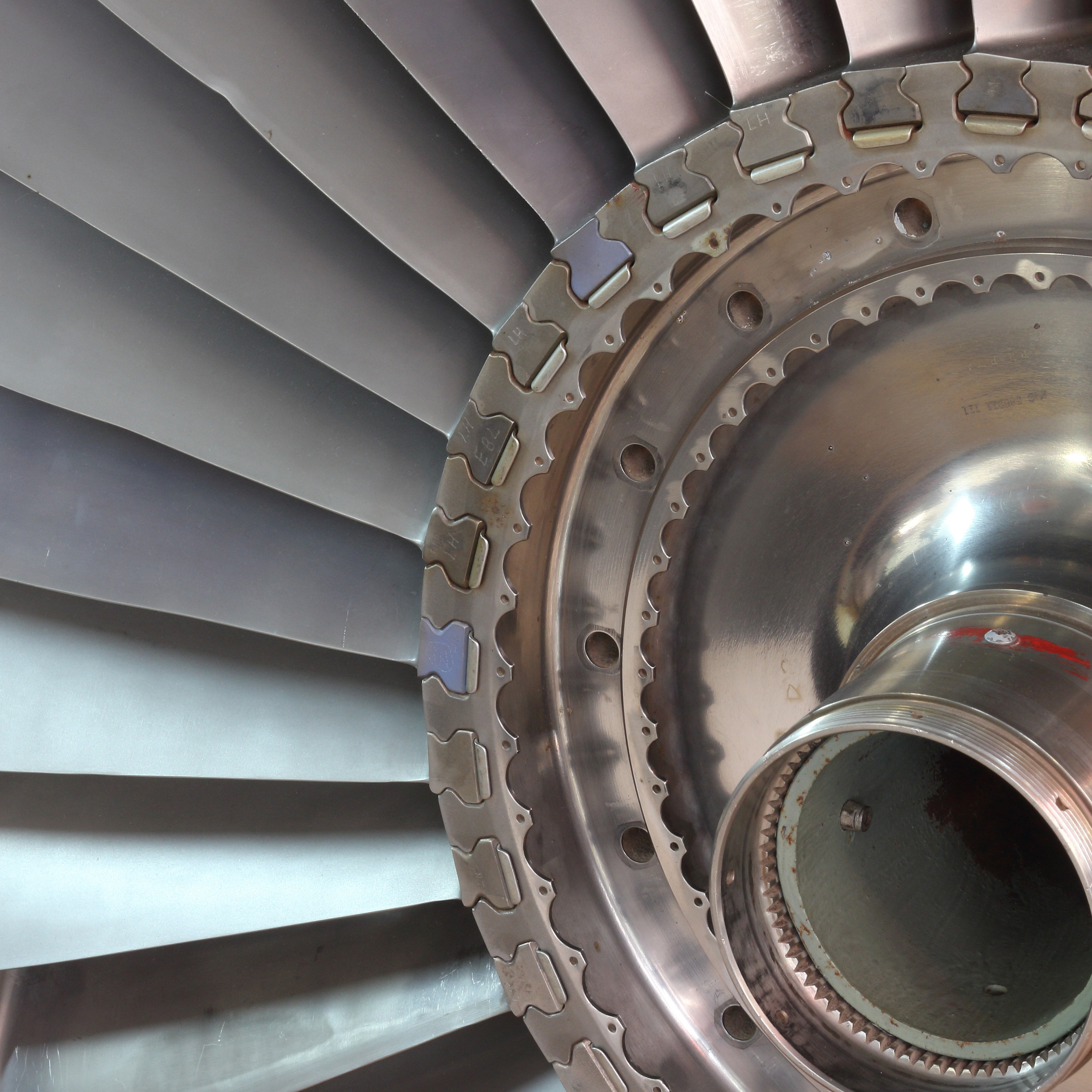 Marking adds nothing to the performance of an aero engine component. It does not make a disc stronger, a BLISK lighter or a casing more efficient. And yet without it, that component cannot be fitted, tracked, maintained or replaced. It is one of the few processes in aerospace manufacturing that adds no value in the engineering sense but is completely non-negotiable in every other.
A few years ago, we discussed this with Aerospace Manufacturing magazine, in a piece about how robotic systems were changing part marking on engine components. Most of what we said then still holds. The technology has moved on and our own range has grown. The pressure on traceability has only increased. So this is the updated version: how robotic marking works on large engine components, why manufacturers invest in it, and how the business case usually gets signed off.
Why aero engine components are marked at all
Aerospace specifications insist that parts carry a permanent, unique identity. The US Department of Defense’s UID requirements and SAE International’s AS9132 direct part marking standard are the two most often quoted, but individual engine manufacturers layer their own specifications on top, covering exactly how a mark should be applied, formatted and positioned on each part.
That identity, usually a combination of human-readable text and a Data Matrix code, acts as a passport for the component. It links the physical part to everything known about its manufacture: the material batch it came from, the machine that cut it, the operator running that machine, the inspection results it passed. If a part ever fails in service, that traceability is what allows investigators to work backwards and find every other component that shares its history.
The problem is the value of the parts being marked. A finished aero engine disc or BLISK can be worth well over £100,000 by the time it reaches the marking operation. It has already absorbed hundreds of hours of machining. A mark applied in the wrong place, at the wrong depth or with a code that fails verification does not just cost a rework loop. In the worst case it condemns the component entirely.
Hand marking still has a place, just a small one
For short runs of low-value parts, hand-held marking equipment remains perfectly adequate, and we still supply plenty of it. But the moment a component is large, expensive and requires multiple marks in precisely controlled positions, manual marking becomes the weakest link in an otherwise tightly controlled process. Operator judgement is simply not a repeatable positioning system.
That is where robotic control comes in.
How a robotic marking cell works
Our multi-axis robotic marking systems are typically used on round and cylindrical engine components: discs, rings, blades and BLISKS, up to around 1.2 metres in diameter as standard, with larger parts handled by arrangement. The robot arm can carry any marking technology, though aerospace manufacturers overwhelmingly specify dot peen, because it produces a permanent, low-stress mark on the nickel alloys and titanium these components are made from.
A typical cycle looks like this. The component is moved into the marking cell, loaded onto a rotary table (by crane, for the heavier forgings) and clamped. The operator scans the part’s existing identity, which calls up the correct marking programme. The robot-mounted marking head then works its way around the component, applying each mark in sequence. The whole process is controlled by our software, linked directly to the customer’s manufacturing execution system so that the data being marked is pulled from the plant’s own records rather than typed in by hand.
The scale of the task is easy to underestimate. A large BLISK may need 15 or more separate marks at different points on its surface, each positioned to a tolerance of 0.1mm. A single engine contains hundreds of parts marked this way. At those tolerances, across that volume, automation is not a luxury.
The next step: fully automated, lights-out marking cells
That describes the cell with an operator in the loop. The latest systems we build now remove the operator altogether.
In these fully automated cells, the disc or BLISK is delivered to the cell by robot, loaded into the cell by robot, and then marked using the same robot-mounted marking head as our more manual systems. Marking and verification run with zero human input, which means the cell is genuinely capable of lights-out operation: parts go in, marked and verified parts come out, and nobody needs to be standing next to it while it happens.
Removing the operator raises an obvious question: who checks the consumables? On a dot peen system, the stylus is the one component that wears, and a worn stylus produces a mark that can fail verification. So, the cell carries several marking heads and selects between them, ensuring there is always a stylus in specification available to apply the mark. And rather than trusting a maintenance schedule, a dedicated vision system inspects the styli themselves and confirms they remain within specification before they are used.
In other words, the cell does not just verify the mark after the event. It verifies the tooling that makes the mark, before the mark is made. On components worth six figures, that order of checking matters.
Why the robot moved to the marking head
When we first applied robotic control to aero components, the parts were small enough that the robot gripped the component and presented it to a stationary marking head. As components have grown, that logic has reversed: the robot now carries the marking head to the part. It sounds like a minor engineering detail, but it is what makes it practical to apply multiple marks across a large, heavy component to tight positional tolerances without endless re-fixturing.
Vision: the part is the reference, and the proof
The vision system earns its place in a robotic cell twice over.
Before marking – The camera locates the datum, bore or feature that a mark must be positioned relative to, and applies an offset to the marking programme automatically. The mark goes where the part actually is, not where the fixture assumes it to be.
After marking – Every mark is verified in the same cell, in the same cycle. The system checks that the marked data is correct, that the Data Matrix code grades to the relevant standard, and that the position meets specification. A bad mark is caught before the part leaves the station, not three operations downstream.
If you want the detail on multi-axis marking and verification of complex geometry, we covered it in depth in our recent article on marking and verifying complex aerospace components. This piece is deliberately about the robotic cell and the business case around it. But the cameras themselves deserve a proper update, because the range has moved on considerably.
An update on the vision cameras: the ReadSmart and VeriSmart 4 range
When the original article was written, the vision system was a single capability. Today we offer an integrated camera range with three distinct levels, all built on Cognex industrial vision platforms and all controlled through our MarkMaster 4 software, so inspection is triggered automatically as part of the marking cycle rather than bolted on afterwards.
ReadSmart 4 – Built around the Cognex DataMan 290 fixed-mount reader, ReadSmart 4 reads laser and dot peen marked Data Matrix codes immediately after marking, confirming the code is readable before the part leaves the station. It can also read existing codes, labels or stickers before marking, either as a data input or as a poka-yoke check. It is the most cost-effective option where the requirement is simply to confirm readability.
ReadSmart+OCR 4 – A step up, using the Cognex In-Sight 2800 vision platform with an inbuilt lighting module. It reads Data Matrix codes and recognises human-readable text in a single inspection, and it is designed for the marks that make standard reading difficult: rough cast surfaces, sawn faces, rough machined components, or VIN characters on painted surfaces of varying colours.
VeriSmart 4 – The full verification system, combining the AI-enabled Cognex In-Sight 2800 camera with a custom Pryor housing and dedicated lighting module. VeriSmart 4 grades Data Matrix codes against the standards aerospace manufacturers actually work to: AS9132, Rolls-Royce JES131, RRES90003, AIM DPM and ISO/IEC 29158, measuring parameters such as symbol contrast, modulation, axial non-uniformity and grid distortion. OCR and OCV tools validate the human-readable text against the expected data, and after each cycle MarkMaster 4 can generate a PDF report of images, results and grades, stored against the part number for full lifecycle traceability.
The aerospace marking cell now uses VeriSmart 4, and the difference an AI-enabled camera makes is real. It verifies marks reliably on materials and finishes that used to need a tolerant spec and careful lighting design. Its high-quality, linear, on-axis illumination is at its best on flat, machined surfaces, which is precisely what the machined faces of discs, rings and BLISKs provide.
The right camera for a given application depends on what the specification demands. If you only need to know the code reads, there is no reason to pay for full verification grading. If your customer requires documented evidence that every mark meets an aerospace standard, VeriSmart 4 is the answer. We will always tell you which one you actually need.
The business case: idle time is where the payback hides
Here is the pattern we see again and again. A manufacturer justifies a robotic cell on its most difficult parts, the large, high-value components that genuinely cannot be marked reliably any other way. Then, once the cell is on the floor, they discover its idle time. Smaller components that were previously hand-marked start going through the cell instead, because it is faster, the traceability record is automatic, and the verification is built in.
The result is that the system ends up marking a far wider range of parts than the original justification assumed, and the payback period shortens accordingly. If you are trying to build a case for robotic marking and the numbers look marginal on your flagship components alone, look at what else the cell could absorb. That is usually where the case is won.
What has changed since the original interview
The fundamentals have not moved. Dot peen remains the aerospace default for direct part marking, and robotic systems remain the answer for large rotatives. What has changed is how far the cell around that marking head has come.
From assisted to autonomous – The original systems still relied on an operator to load the part, scan it and start the cycle. The cells we are building now handle all of that themselves, with robotic part delivery and loading, automatic marking head selection, and no requirement for anyone to be present. The step from a manned cell to a genuinely lights-out one is the single biggest change in this technology since we first applied robotic control to engine components.
A step change in vision performance – The cameras have not simply improved, they have changed category. AI-enabled inspection copes with the surface conditions, mark contrast variation and component geometry that used to require careful lighting design and a tolerant specification. Marks that once needed an operator to make a judgement call are now graded automatically, repeatably, and with a documented result attached to the part number. Vision has also expanded beyond checking the mark to checking the process that produces it, including the condition of the marking styli themselves.
A more polished, more proven solution – We have built and supplied a great many of these systems since that interview, and every one has fed something back into the design. Fixturing, guarding, head configuration, software workflow, maintenance access and cycle time have all been refined against real production experience rather than a drawing board. A manufacturer buying a robotic marking cell today is not commissioning a bespoke prototype. They are buying a mature platform that has already earned its place on aerospace production lines, and which we continue to improve with each build.
Traceability expectations have tightened – Across every sector we serve, and aerospace continues to set the pace. The mark is no longer the end of the process. It is the anchor for everything digital that follows it, and the evidence that the mark was applied correctly now matters almost as much as the mark itself.
Talk to the people who build these systems
Every robotic marking cell we supply is designed, built and programmed at our factory in Sheffield, where we have been making marks permanent since 1849. When you talk to us about an aerospace marking requirement, you are talking directly to the engineers who will design the system.
If you are weighing up robotic marking for aero-engine components, or trying to make the business case stack up, get in touch and talk it through with our team.
This article updates an interview originally published by Aerospace Manufacturing magazine (‘A Marked Improvement’). Our thanks to the Aerospace Manufacturing team.